
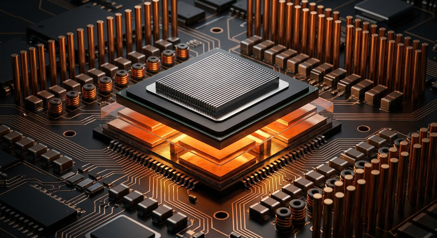
A modern AI accelerator does not run on the 12 volts that travel across the motherboard. It asks for 0.6 to 0.9 volts, but with a current measured in thousands of amps. A 700-watt chip running at 0.8 volts draws 875 amps; the largest modules are already around 1,000. For comparison, the main breaker panel of an average home delivers 40 or 50. The interesting question is not how that chip is manufactured, but how those currents are delivered without the copper carrying them turning red hot.
The problem is not the voltage, it is the drop
The power dissipated by a parasitic resistance follows a simple formula: P = I²R. At 1,000 amps, every milliohm of copper the current crosses turns into a kilowatt of heat. And a milliohm is very little: a short stretch of copper trace on a board already exceeds it. If the regulator sat at the edge of the board and the current had to cross 20 centimetres of copper, the voltage drop could be several tenths of a volt, more than the chip’s own tolerance margin, usually ±3% (about 25 millivolts). The processor would run out of voltage before it started computing.
That is why the whole design revolves around one obsession: shortening the path. The network that distributes power from the converter to the transistors is called the PDN (power delivery network) and it is measured in milliohms and picoseconds. It is not enough for the voltage to be right on average; it must stay inside a very narrow window while the load jumps from 200 to 1,000 amps in microseconds.
From 48 volts to 0.8: two stages and many switches
The alternating current entering a data centre is first converted to direct current. It used to be distributed at 12 volts inside the rack, but at 12 volts moving 120 kilowatts takes 10,000 amps and copper bars sturdy enough to hold up a car. The industry moved to 48 volts (the Open Rack standard from the Open Compute Project) and some operators are already testing 400 volts DC. The reason is purely quadratic: multiplying the voltage by four divides the current by four and cuts losses in the wiring sixteenfold.
The next step is taken by a step-down converter, or buck, the integrated circuit that acts as a DC transformer. Its structure is almost elementary: two switching MOSFETs, an inductor that stores energy and an output capacitor. One side of the inductor is connected alternately to the input and to ground; the duty cycle (the fraction of time it is connected to the input) sets the output voltage. With 48 volts in and 0.8 out, that cycle is 1.7%: pulses a few tens of nanoseconds long. Switching for such a short time at hundreds of kilohertz demands very fast transistors and a controller that cannot be wrong by even a nanosecond.
Hence the interest in gallium nitride (GaN). These transistors have lower on-resistance and parasitic capacitance than silicon, switch faster and allow higher operating frequencies, which shrinks the inductor and reduces switching losses. With silicon, a realistic design converts 48 volts to an intermediate 6 or 12 volts and then steps down to 0.8; with GaN it can be done in a single stage, closer to the chip and with fewer components.
Sixteen phases taking turns
A single converter cannot deliver 1,000 amps without absurd components. The answer is multiphase operation: instead of one buck, 16, 20 or 24 are placed in parallel, each with its own inductor, and they are switched out of step with one another. Spreading the full cycle across the phases adds up the current reaching the chip and largely cancels the ripple: if the phases are properly staggered, the output ripple falls as if the frequency had been multiplied by the number of phases. Each phase moves 40 to 60 amps, and the controller decides how many to turn on according to the load. At light load it shuts phases down to avoid wasting energy switching for nothing; at full load it turns them all on.
Switching is not free. Every transistor has an on-resistance (Rds(on)) and every transition costs energy in the parasitic capacitances. A well-designed converter reaches 90 to 95% efficiency. The rest becomes heat inside the regulator itself: with 1,000 watts of load, 50 to 100 watts are dissipated in the MOSFETs and inductors, not in the chip. That is why the regulators of current accelerators sit against the cold plate and the coolant flows through them too.
Capacitors buy time
The controller is not instantaneous. Hundreds of nanoseconds pass between detecting a load change and adjusting the duty cycle, an eternity for a chip that draws 1,000 amps in a microsecond. In that gap the energy comes from capacitors: first the ceramics on the board itself, then the polymer and electrolytic parts with larger capacity. Absorbing 1,000 amps for 100 nanoseconds without letting the voltage fall more than 50 millivolts requires an effective capacitance of several millifarads, spread across hundreds of components with tiny parasitic resistance and inductance. Every millimetre of trace between capacitor and chip adds inductance, and inductance prevents the current from arriving in time.
Hence the push for vertical power delivery: placing the regulator under the socket, on the back of the board, and sending current straight up through thousands of vias. The path is measured in millimetres and the inductance collapses. Intel already tried it with regulators integrated into the package (FIVR), and the industry is coming back to power modules beneath the substrate.
Talking to the chip
The processor does not simply receive voltage. It asks for it. Through a serial management bus — SVID on Intel platforms, AVSBus or PMBus in other designs — it states the voltage code it needs for each frequency and idle state. The controller adjusts the output and also applies a technique called adaptive positioning: when current rises, it lets the voltage droop by a few millivolts in a controlled way (the load line). That extra margin prevents oscillation and reduces consumption. The same bus returns current, temperature and power telemetry, which the firmware uses to lower frequencies if the regulator approaches its limit.
The result is a control loop that runs thousands of times per second and coexists with an ageing problem: electrolytic capacitors dry out, their capacitance falls and their resistance rises. A regulator that ages badly can cause unexplained shutdowns years later. Server designs use polymer and tantalum capacitors, derate the voltage and monitor impedance to get ahead of it.
The next bottleneck is copper
With 1,200 watts per module and racks above 120 kilowatts, the limit is no longer the transistor: it is transport. That is why conversion is moving closer to the chip, distribution is rising to 48 volts and 800 volts DC is being studied for AI racks. Every volt lost along the way must be removed with cooling, and cooling costs space, water and energy. In the end, the performance of an AI data centre is decided in good part on a few square centimetres of copper, where 1,000 amps must arrive intact at 0.8 volts.